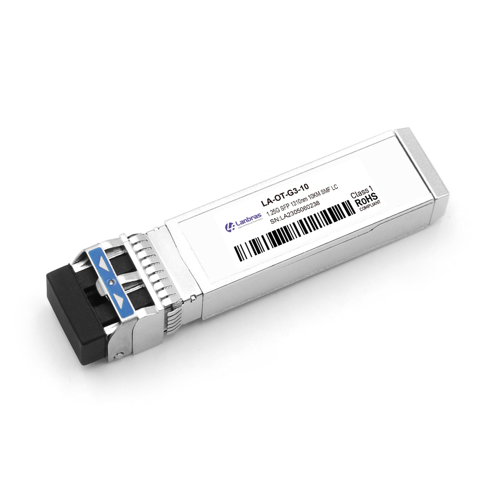
Designed for use in 10-Gigabit Ethernet links up to 80km over single mode fiber. The module consists of CWDM EML Laser, APD and Preamplifier in a high-integrated optical sub-assembly.

Designed for use in 10-Gigabit Ethernet links up to 80km over single mode fiber. The module consists of CWDM EML Laser, APD and Preamplifier in a high-integrated optical sub-assembly.
Designed for use in 10-Gigabit Ethernet links up to 80km over single mode fiber. The module consists of CWDM EML Laser, APD and Preamplifier in a high-integrated optical sub-assembly. Digital diagnostics functions are available via a 2-wire serial interface, as specified in SFF 8472. The module data link up to 80km in 9/125um single mode fiber.
Features
● Compliant to SFP+ SFF-8431 and SFF-8432 Hot-pluggable SFP+ footprint
● Supports 9.5 to 11.3Gb/s bit rates
● Power dissipation < 1.5W
● Single 3.3V power supply
● Maximum link length of 80km
● CWDM wavelength EML transmitter, APD photo-detector
● Duplex LC connector
● Power dissipation < 1.5W
● Built-in digital diagnostic functions
● Case temperature range: 0°C to 70°C
Standard
● Compliant with SFF-8472 SFP+ MSA
● Compliant to SFP+ SFF-8431 and SFF-8432
● Compliant to 802.3ae 10GBASE-ZR
Absolute Maximum Ratings
|
Parameter |
Symbol |
Min. |
Typ. |
Max. |
Unit |
Note |
|
Storage Temperature |
Ts |
-40 |
|
85 |
ºC |
|
|
Storage Ambient Humidity |
HA |
5 |
|
85 |
% |
|
|
Power Supply Voltage |
VCC |
-0.5 |
|
4 |
V |
|
|
Signal Input Voltage |
|
-0.3 |
|
Vcc+0.3 |
V |
|
|
Receiver Damage Threshold |
|
+4 |
|
|
dBm |
|
Operation Environment
|
Parameter |
Symbol |
Min. |
Typ. |
Max. |
Unit |
Note |
|
Operating Case Temperature |
Tcase |
0 |
|
70 |
ºC |
Note (1) |
|
Ambient Humidity |
HA |
5 |
|
85 |
% |
|
|
Power Supply Voltage |
VCC |
3.14 |
3.3 |
3.46 |
V |
|
|
Power Supply Current |
ICC |
|
|
450 |
mA |
|
|
Power Supply Noise Rejection |
|
|
|
100 |
mVp-p |
100Hz to 1MHz |
|
Transmission Distance |
|
|
|
80 |
km |
|
|
Coupled fiber |
Single mode fiber |
ITU-T G.653 |
||||
Note: -10 to 60degC with 1.5m/s airflow
Optical Characteristics
|
Parameter |
Symbol |
Min. |
Typ. |
Max. |
Unit |
Note |
|
Transmitter |
||||||
|
Average Launched Power |
PO |
-2 |
|
+5 |
dBm |
Note (1) |
|
Extinction Ratio |
ER |
6 |
|
|
dB |
|
|
Center Wavelength |
λc |
1470 |
|
1610 |
nm |
|
|
Center Wavelength Space |
|
|
20 |
|
nm |
|
|
Spectrum Band Width (RMS) |
σ |
|
|
1.0 |
nm |
|
|
SMSR |
|
30 |
|
|
dB |
|
|
Transmitter OFF Output Power |
POff |
|
|
-40 |
dBm |
|
|
TX Jitter (peak-peak) |
Txj |
|
|
0.1 |
UI |
|
|
TX Jitter (RMS) |
Txjrms |
|
|
0.01 |
UI |
|
|
Transmitter and Dispersion Penalty |
TDP |
|
|
3.0 |
dB |
|
|
Output Eye Mask |
Compliant with IEEE 0802.3ae |
|
|
|||
|
Receiver |
||||||
|
Input Optical Wavelength |
λ |
1270 |
|
1610 |
nm |
|
|
Receiver Sensitivity |
|
|
|
-22 |
dBm |
Note (2) |
|
Input Saturation Power (Overload) |
Psat |
-8 |
|
|
dBm |
|
|
LOS Detect -Assert Power |
PA |
-36 |
|
|
dBm |
|
|
LOS Detect - Deassert Power |
PD |
|
|
-23 |
dBm |
|
|
LOS Detect Hysteresis |
PHYS |
2 |
|
|
dB |
|
Note:
1. Launched power (avg.) is power coupled into a single mode fiber with connector. (Before of Life)
2. Measured with conformance test signal for BER = 10^–12.@10.3125Gbps, PRBS=2^31-1, NRZ
Electrical Characteristics
|
Parameter |
Symbol |
Min. |
Typ. |
Max. |
Unit |
Note |
|
|
Transmitter |
|||||||
|
Differential line input Impedance |
RIN |
|
100 |
|
Ohm |
|
|
|
Differential Data Input Swing |
VDT |
300 |
|
700 |
mVp-p |
|
|
|
Transmit Disable Voltage |
Vdis |
2 |
|
Vcc |
V |
LVTTL |
|
|
Transmit Enable Voltage |
Ven |
Vee |
|
Vee+0.8 |
V |
||
|
Receiver |
|||||||
|
Differential Data Output Swing |
VDR |
400 |
|
850 |
mVp-p |
Note (1) |
|
|
LOS Output Voltage-High |
VLOSH |
Vee |
|
Vee+0.8 |
V |
LVTTL |
|
|
LOS Output Voltage-Low |
VLOSL |
2 |
|
VccHOST |
V |
||
Note: Into 100Ω differential termination.
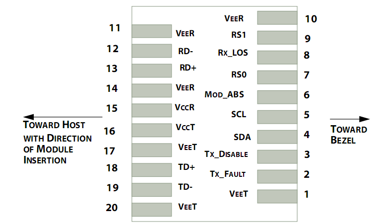
Pin Description

|
Pin |
Symbol |
Name/Description |
Note |
|
1 |
VEET |
Transmitter Ground (Common with Receiver Ground) |
1 |
|
2 |
TFAULT |
Transmitter Fault. |
2 |
|
3 |
TDIS |
Transmitter Disable. Laser output disabled on high or open. |
3 |
|
4 |
SDA |
2-wire Serial Interface Data Line |
4 |
|
5 |
SCL |
2-wire Serial Interface Clock Line |
4 |
|
6 |
MOD_ABS |
Module Absent. Grounded within the module |
4 |
|
7 |
RS0 |
Rate Select 0 |
5 |
|
8 |
LOS |
Loss of Signal indication. Logic 0 indicates normal operation. |
6 |
|
9 |
RS1 |
No connection required |
1 |
|
10 |
VEER |
Receiver Ground (Common with Transmitter Ground) |
1 |
|
11 |
VEER |
Receiver Ground (Common with Transmitter Ground) |
1 |
|
12 |
RD- |
Receiver Inverted DATA out. AC Coupled |
|
|
13 |
RD+ |
Receiver Non-inverted DATA out. AC Coupled |
|
|
14 |
VEER |
Receiver Ground (Common with Transmitter Ground) |
1 |
|
15 |
VCCR |
Receiver Power Supply |
|
|
16 |
VCCT |
Transmitter Power Supply |
|
|
17 |
VEET |
Transmitter Ground (Common with Receiver Ground) |
1 |
|
18 |
TD+ |
Transmitter Non-Inverted DATA in. AC Coupled. |
|
|
19 |
TD- |
Transmitter Inverted DATA in. AC Coupled. |
|
|
20 |
VEET |
Transmitter Ground (Common with Receiver Ground) |
1 |
Notes:
1. TX Fault is an open collector output, which should be pulled up with a 4.7k~10kΩ resistor on the host board to a voltage between 2.0V and Vcc+0.3V. Logic 0 indicates normal operation; logic 1 indicates a laser fault of some kind. In the low state, the output will be pulled to less than 0.8V.
2. TX Disable is an input that is used to shut down the transmitter optical output. It is pulled up within the module with a 4.7k~10kΩ resistor. Its states are:
Low (0~0.8V): Transmitter on
(>0.8V, <2.0V): Undefined
High (2.0~3.3V): Transmitter Disabled
Open: Transmitter Disabled
3. MOD-DEF 0,1,2 is the module definition pins. They should be pulled up with a 4.7k~10kΩ resistor on the host board. The pull-up voltage shall be VccT or VccR.
MOD-DEF 0 is grounded by the module to indicate that the module is present
MOD-DEF 1 is the clock line of two wire serial interface for serial ID
MOD-DEF 2 is the data line of two wire serial interface for serial ID
4. LOS is an open collector output, which should be pulled up with a 4.7k~10kΩ resistor on the host board to a voltage between 2.0V and Vcc+0.3V. Logic 0 indicates normal operation; logic 1 indicates loss of signal. In the low state, the output will be pulled to less than 0.8V.
5. These are the differential receiver output. They are internally AC-coupled 100Ω differential lines which should be terminated with 100Ω (differential) at the user SERDES.
6. These are the differential transmitter inputs. They are AC-coupled, differential lines with 100Ω differential termination inside the module.
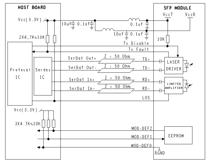
Recommended Application Circuit

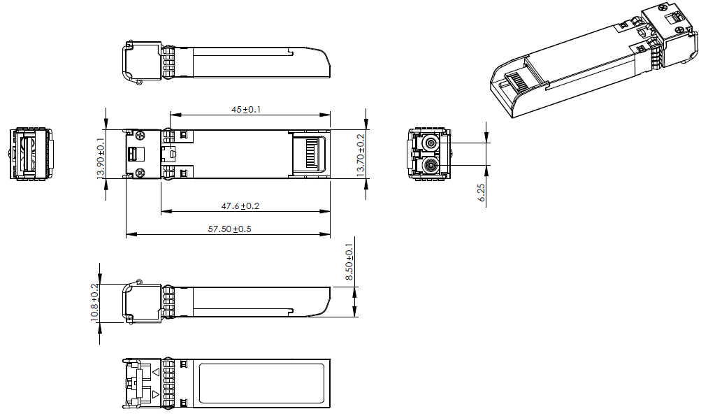
Outline Drawings (mm)

Regulatory Compliance
|
Feature |
Reference |
Performance |
|
Electrostatic disge (ESD) |
IEC/EN 61000-4-2 |
Compatible with standards |
|
Electromagnetic Interference (EMI) |
FCC Part 15 Class B EN 55022 Class B (CISPR 22A) |
Compatible with standards |
|
Laser Eye Safety |
FDA 21CFR 1040.10, 1040.11 IEC/EN 60825-1, 2 |
Class 1 laser product |
|
Component Recognition |
IEC/EN 60950, UL |
Compatible with standards |
|
ROHS |
2002/95/EC |
Compatible with standards |
|
EMC |
EN61000-3 |
Compatible with standards |
| Ordering Information |
|---|
| Date | Version | Description | Download |
|---|---|---|---|
| 2024-05-07 | V2.0 | Datasheet_10G CWDM SFP+ 1470nm~1610nm 80km_LA-OT-10GCW46-80_V2.Y.pdf | |
| Photo | Model | Description |
|---|