
LA-CFP-ER4/OTU4, 100G CFP2 ER4 optical transceiver integrates the transmit and receive path onto one module. On the transmit side, four lanes of serial data streams are recovered.
LA-CFP-ER4/OTU4, 100G CFP2 ER4 optical transceiver integrates the transmit and receive path onto one module. On the transmit side, four lanes of serial data streams are recovered.
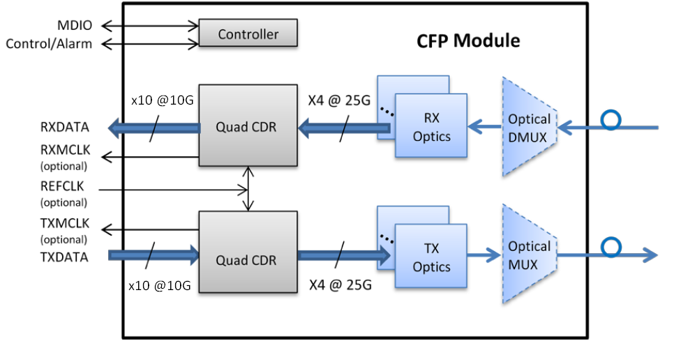
LA-CFP-ER4/OTU4, 100G CFP2 ER4 optical transceiver integrates the transmit and receive path onto one module. On the transmit side, four lanes of serial data streams are recovered, retimed,and passed on to four laser drivers, which control four electric-absorption modulated lasers (EMLs) with 1296, 1300, 1305, and 1309 nm center wavelengths. The optical signals are then multiplexed into a single-mode fiber through an industry-standard LC connector.On the receive side, 4 lanes of optical data streams are optically demultiplexed by an integrated optical demultiplexer. Each data steam is recovered by a PIN photodetector and transimpedance amplifier, retimed, and passed on to an output driver. This module features a hot-pluggable electrical interface, low power consumption, and MDIO management interface.
Features
● Supports 103.1Gbps to 112Gbps bit rates
● Duplex LC connector
● Hot pluggable
● 4x28Gb/s DFB-based LAN-WDM transmitter
● 10x10G MLD electrical interface
● Applicable for 40km SMF connection
● Low power consumption, < 18W
● Digital Diagnostic Monitor Interface
● MDIO Communication Interface
● Compliant with 100GBASE-ER4 and OTU4
● Operating case temperature: Commercial:0 to 70 °C
Functional Diagram
Absolute Maximum Ratings
|
Parameter |
Symbol |
Min. |
Max. |
Unit |
Note |
|
Supply Voltage |
Vcc |
-0.5 |
4.0 |
V |
|
|
Storage Temperature |
TS |
-40 |
85 |
°C |
|
|
Relative Humidity |
RH |
0 |
85 |
% |
|
|
Rx Damage Threshold,per Lane |
PRdmg |
5.5 |
|
dBm |
|
Note: Stress in excess of the maximum absolute ratings can cause permanent damage to the transceiver.
Recommended Operating Conditions
|
Parameter |
Symbol |
Min. |
Typ |
Max. |
Unit |
Note |
|
Data Rate |
DR |
|
103.2 |
112 |
Gb/s |
|
|
Supply Voltage |
Vcc |
3.14 |
3.3 |
3.46 |
V |
|
|
Operating Case Temp. |
Tc |
0 |
|
70 |
°C |
|
Electrical Characteristics (Top=0~70℃, Vcc=3.2~3.4V)
(Tested under recommended operating conditions,unless otherwise noted)
|
Parameter |
Symbol |
Min |
Typ |
Max |
Unit |
Notes |
|
Supply Current |
Icc |
|
|
5 |
A |
|
|
Supply Voltage |
Vcc |
3.2 |
|
3.4 |
V |
|
|
Transmitter |
||||||
|
Signaling rate per lane |
DRPL |
|
|
11.2 |
Gb/s |
|
|
Input differential impedance |
Rin |
|
100 |
|
Ω |
|
|
Differential data imput swing per lane |
Vin,pp |
|
|
760 |
mV |
|
|
Data input rise time tolerance |
Tr |
24 |
|
|
Ps |
1 |
|
Data input fall time tolerance |
Tf |
24 |
|
|
ps |
1 |
|
Electrical input eye mask defintion |
{X1,X2}
{Y1,Y2} |
{0.2,0.5}
{136,380} |
UI
mV |
|
||
|
Power Supply Noise Tolerance |
Vrip |
Per CFP MSA Specification |
|
|||
|
Receiver |
||||||
|
Signaling rate per lane |
DRPL |
|
|
11.2 |
Gb/s |
|
|
Differential data output swing per lane |
Vout,pp |
|
|
760 |
mV |
|
|
Data output rise time tolerance |
Tr |
24 |
80 |
|
ps |
1 |
|
Data output fall time tolerance |
Tf |
24 |
80 |
|
ps |
1 |
|
Electrical input eye mask defintion |
{X1,X2}
{Y1,Y2} |
{0.2,0.5}
{136,380} |
UI
mV |
|
||
|
Power Supply Noise Tolerance |
Vrip |
Per CFP MSA Specification |
|
|||
Notes:
1.20%~80%
Optical Characteristics (Top=0~70℃, Vcc=3.2~3.4V)
(Tested under recommended operating conditions,unless otherwise noted)
|
Parameter |
Symbol |
Unit |
Min |
Typ |
Max |
Notes |
|||
|
Transmitter |
|||||||||
|
Signaling rate, each lane |
|
GBd |
25.78125 ±100 ppm |
100GBase-LR4,1 |
|||||
|
27.9525 ±20 ppm |
OTU4,1 |
||||||||
|
Four Lane Wavelength Range |
λ1 |
nm |
1294.53 |
1295.56 |
1296.59 |
|
|||
|
λ2 |
1299.02 |
1300.05 |
1301.09 |
|
|||||
|
λ3 |
1303.54 |
1304.58 |
1305.63 |
|
|||||
|
λ4 |
1308.09 |
1309.14 |
1310.19 |
|
|||||
|
Total launch power |
Pout |
dBm |
|
|
10.5 |
100GBase-ER4 |
|||
|
|
|
10 |
OTU4 |
||||||
|
Average launch power, each lane |
Pavg |
dBm |
-2.9 |
|
2.9 |
100GBase-ER4,2 |
|||
|
-6 |
|
4 |
OTU4,2 |
||||||
|
Optical modulation amplitude, each lane (OMA)2 |
OMA |
dBm |
-1.3 |
|
4.5 |
|
|||
|
Difference in launch power between any two lanes (OMA) |
|
dB |
|
|
5 |
|
|||
|
Extinction ratio |
ER |
dB |
4 |
|
|
100GBase-ER4 |
|||
|
4 |
|
6.5 |
OTU4 |
||||||
|
Side-mode suppression ratio |
SMSR |
dB |
30 |
|
|
|
|||
|
Transmitter and dispersion penalty, each lane |
TDP |
dB |
|
|
2.2 |
|
|||
|
Optical return loss tolerance |
|
dB |
|
|
20 |
|
|||
|
Transmitter reflectance3 |
|
dB |
|
|
–12 |
|
|||
|
Transmitter eye mask {X1, X2, X3, Y1, Y2, Y3} |
|
|
{0.25, 0.4, 0.45, 0.25, 0.28, 0.4} |
100GBase-ER4 |
|||||
|
Optical Receiver Characteristics |
|||||||||
|
Receive Rate for Each Lane |
|
Gbps |
|
25.78125 |
27.9525 |
3 |
|||
|
Overload Input Optical Power |
Pmax |
dBm |
5.5 |
|
|
|
|||
|
Average Receive Power for Each
Lane |
Pin |
dBm |
-20.9 |
|
4.5 |
4 |
|||
|
Receiver Sensitivity(OMA)per lane |
Psens1 |
dBm |
|
|
-17.9 |
|
|||
|
Stressed Sensitivity(OMA) per lane |
Psens2 |
dBm |
|
|
-15.9 |
|
|||
|
Return Loss |
RL |
dB |
-26 |
|
|
|
|||
|
Receiver Electrical 3dB upper cutoff frequency, per lane |
|
GHz |
|
|
31 |
|
|||
|
Los De-Assert |
Pd |
dBm |
|
|
-19 |
|
|||
|
Los Assert |
Pa |
dBm |
|
|
-21 |
|
|||
|
Loss Hysteresis |
Pd-Pa |
dBm |
1 |
|
|
|
|||
Notes:
1. Transmitter consists of 4 lasers operating at 25.78Gb/s each for 100GBASE-LR, 27.95Gb/s each for OTU4
2. Minimum value is informative.
3. Receiver consists of 4 photodetectors operating at 25.78Gb/s each each for 100GBASE-LR, 27.95Gb/s each for OTU4
4. Minimum value is informative, equals min TxOMA with infinite ER and max channel ion loss.
Pin Description
|
|
Top View |
|
Bottom View |
|
148 |
GND |
1 |
3.3V_GND |
|
147 |
REFCLKn |
2 |
3.3V_GND |
|
146 |
REFCLKp |
3 |
3.3V_GND |
|
145 |
GND |
4 |
3.3V_GND |
|
144 |
N.C. |
5 |
3.3V_GND |
|
143 |
N.C. |
6 |
3.3V |
|
142 |
GND |
7 |
3.3V |
|
141 |
TX9n |
8 |
3.3V |
|
140 |
TX9p |
9 |
3.3V |
|
139 |
GND |
10 |
3.3V |
|
138 |
TX8n |
11 |
3.3V |
|
137 |
TX8p |
12 |
3.3V |
|
136 |
GND |
13 |
3.3V |
|
135 |
TX7n |
14 |
3.3V |
|
134 |
TX7p |
15 |
3.3V |
|
133 |
GND |
16 |
3.3V_GND |
|
132 |
TX6n |
17 |
3.3V_GND |
|
131 |
TX6p |
18 |
3.3V_GND |
|
130 |
GND |
19 |
3.3V_GND |
|
129 |
TX5n |
20 |
3.3V_GND |
|
128 |
TX5p |
21 |
VND_IO_A |
|
127 |
GND |
22 |
VND_IO_B |
|
126 |
TX4n |
23 |
GND |
|
125 |
TX4p |
24 |
TX_MCLKn |
|
124 |
GND |
25 |
TX_MCLKp |
|
123 |
TX3n |
26 |
GND |
|
122 |
TX3p |
27 |
VND_IO_C |
|
121 |
GND |
28 |
VND_IO_D |
|
120 |
TX2n |
29 |
VND_IO_E |
|
119 |
TX2p |
30 |
PRG_CNTL1 |
|
118 |
GND |
31 |
PRG_CNTL2 |
|
117 |
TX1n |
32 |
PRG_CNTL3 |
|
116 |
TX1p |
33 |
PRG_ALRM1 |
|
115 |
GND |
34 |
PRG_ALRM2 |
|
114 |
TX0n |
35 |
PRG_ALRM3 |
|
113 |
TX0p |
36 |
TX_DIS |
|
112 |
GND |
37 |
MOD_LOPWR |
|
|
Top View |
|
Bottom View |
|
111 |
GND |
38 |
MOD_ABS |
|
110 |
N.C. |
39 |
MOD_RSTn |
|
109 |
N.C. |
40 |
RX_LOS |
|
108 |
GND |
41 |
GLB_ALRMn |
|
107 |
RX9n |
42 |
PRTADR4 |
|
106 |
RX9p |
43 |
PRTADR3 |
|
105 |
GND |
44 |
PRTADR2 |
|
104 |
RX8n |
45 |
PRTADR1 |
|
103 |
RX8p |
46 |
PRTADR0 |
|
102 |
GND |
47 |
MDIO |
|
101 |
RX7n |
48 |
MDC |
|
100 |
RX7p |
49 |
GND |
|
99 |
GND |
50 |
VND_IO_F |
|
98 |
RX6n |
51 |
VND_IO_G |
|
97 |
RX6p |
52 |
GND |
|
96 |
GND |
53 |
VND_IO_H |
|
95 |
RX5n |
54 |
VND_IO_J |
|
94 |
RX5p |
55 |
3.3V_GND |
|
93 |
GND |
56 |
3.3V_GND |
|
92 |
RX4n |
57 |
3.3V_GND |
|
91 |
RX4p |
58 |
3.3V_GND |
|
90 |
GND |
59 |
3.3V_GND |
|
89 |
RX3n |
60 |
3.3V |
|
88 |
RX3p |
61 |
3.3V |
|
87 |
GND |
62 |
3.3V |
|
86 |
RX2n |
63 |
3.3V |
|
85 |
RX2p |
64 |
3.3V |
|
84 |
GND |
65 |
3.3V |
|
83 |
RX1n |
66 |
3.3V |
|
82 |
RX1p |
67 |
3.3V |
|
81 |
GND |
68 |
3.3V |
|
80 |
RX0n |
69 |
3.3V |
|
79 |
RX0p |
70 |
3.3V_GND |
|
78 |
GND |
71 |
3.3V_GND |
|
77 |
RX_MCLKn |
72 |
3.3V_GND |
|
76 |
RX_MCLKp |
73 |
3.3V_GND |
|
75 |
GND |
74 |
3.3V_GND |
|
Pin |
Name |
I/O |
Logic |
Description |
|
1 |
3.3V_GND |
|
|
3.3V Module Supply Voltage Return Ground, internally connected to Signal Ground |
|
2 |
3.3V_GND |
|
|
3.3V Module Supply Voltage Return Ground, internally connected to Signal Ground |
|
3 |
3.3V_GND |
|
|
3.3V Module Supply Voltage Return Ground, internally connected to Signal Ground |
|
4 |
3.3V_GND |
|
|
3.3V Module Supply Voltage Return Ground, internally connected to Signal Ground |
|
5 |
3.3V_GND |
|
|
3.3V Module Supply Voltage Return Ground, internally connected to Signal Ground |
|
6 |
3.3V |
|
|
3.3V Module Supply Voltage |
|
7 |
3.3V |
|
|
3.3V Module Supply Voltage |
|
8 |
3.3V |
|
|
3.3V Module Supply Voltage |
|
9 |
3.3V |
|
|
3.3V Module Supply Voltage |
|
10 |
3.3V |
|
|
3.3V Module Supply Voltage |
|
11 |
3.3V |
|
|
3.3V Module Supply Voltage |
|
12 |
3.3V |
|
|
3.3V Module Supply Voltage |
|
13 |
3.3V |
|
|
3.3V Module Supply Voltage |
|
14 |
3.3V |
|
|
3.3V Module Supply Voltage |
|
15 |
3.3V |
|
|
3.3V Module Supply Voltage |
|
16 |
3.3V_GND |
|
|
3.3V Module Supply Voltage Return Ground, internally connected to Signal Ground |
|
17 |
3.3V_GND |
|
|
3.3V Module Supply Voltage Return Ground, internally connected to Signal Ground |
|
18 |
3.3V_GND |
|
|
3.3V Module Supply Voltage Return Ground, internally connected to Signal Ground |
|
19 |
3.3V_GND |
|
|
3.3V Module Supply Voltage Return Ground, internally connected to Signal Ground |
|
20 |
3.3V_GND |
|
|
3.3V Module Supply Voltage Return Ground, internally connected to Signal Ground |
|
21 |
VND_IO_A |
I/O |
|
Module Vendor I/O A. Do Not Connect! |
|
22 |
VND_IO_B |
I/O |
|
Module Vendor I/O B. Do Not Connect! |
|
23 |
GND |
|
|
|
|
24 |
TX_MCLKn |
O |
|
Freq = Optical rate/32. Utilized for optical waveform testing. Not for normal use. |
|
25 |
TX_MCLKp |
O |
|
Freq = Optical rate/32. Utilized for optical waveform testing. Not for normal use. |
|
26 |
GND |
|
|
|
|
27 |
VND_IO_C |
I/O |
|
Module Vendor I/O C. Do Not Connect!
|
|
28 |
VND_IO_D |
I/O |
|
Module Vendor I/O D Do Not Connect!
|
|
29 |
VND_IO_E |
I/O |
|
Module Vendor I/O E. Do Not Connect!
|
|
30 |
PRG_CNTL1 |
I |
LVCMOS w/PUR |
Programmable Control 1 set over MDIO, Default: TRXIC_RSTn, TX & RX ICs reset, "0": reset; "1" or NC: enabled (i.e., not used). |
|
31 |
PRG_CNTL2 |
I |
LVCMOS w/PUR |
Programmable Control 2 set over MDIO, Default: Hardware Interlock LSB, "00": ≤8W; "01": ≤16W; "10": ≤24W; "11" or NC: ≤32W (i.e., not used). |
|
32 |
PRG_CNTL3 |
I |
LVCMOS w/PUR |
Programmable Control 3 set over MDIO, Default: Hardware Interlock LSB, "00": ≤8W; "01": ≤16W; "10": ≤24W; "11" or NC: ≤32W (i.e., not used). |
|
33 |
PRG_ALRM1
|
O |
LVCMOS |
Programmable Alarm 1 set over MDIO, Default: HIPWR_ON, "1": module power up completed; "0": module not high powered up. |
|
34 |
PRG_ALRM2
|
O |
LVCMOS |
Programmable Alarm 2 set over MDIO, Default: MOD_READY, "1": Ready; "0": not Ready. |
|
35 |
PRG_ALRM3
|
O |
LVCMOS |
Programmable Alarm 3 set over MDIO, Default: MOD_FAULT, fault detected, "1": Fault; "0": No Fault. |
|
36 |
TX_DIS |
I |
LVCMOS w/PUR |
Transmitter Disable for all lanes, "1" or NC = transmitter disabled, "0" = transmitter enabled |
|
37 |
MOD_LOPWR |
I |
LVCMOS w/PUR |
Module Low Power Mode. "1" or NC: module in low power (safe) mode, "0": power-on enabled |
|
38 |
MOD_ABS |
O |
GND |
Module Absent. "1" or NC: module absent, "0": module present, Pull Up Resistor on Host |
|
39 |
MOD_RSTn |
I |
LVCMOS w/PDR |
Module Reset. "0" resets the module, "1" or NC = module enabled, Pull Down Resistor in Module |
|
40 |
RX_LOS |
O |
LVCMOS |
Receiver Loss of Optical Signal, "1": low optical signal, "0": normal condition |
|
41 |
GLB_ALRMn |
O |
LVCMOS |
Global Alarm. “0": alarm condition in any MDIO Alarm register, "1": no alarm condition, Open Drain, Pull Up Resistor on Host |
|
42 |
PRTADR4 |
I |
1.2V CMOS |
MDIO Physical Port address bit 4 |
|
43 |
PRTADR3 |
I |
1.2V CMOS |
MDIO Physical Port address bit 3 |
|
44 |
PRTADR2 |
I |
1.2V CMOS |
MDIO Physical Port address bit 2 |
|
45 |
PRTADR1 |
I |
1.2V CMOS |
MDIO Physical Port address bit 1 |
|
46 |
PRTADR0 |
I |
1.2V CMOS |
MDIO Physical Port address bit 0 |
|
47 |
MDIO |
I/O |
1.2V CMOS |
Management Data I/O bi-directional data (electrical specs as per 802.3ae and ba) |
|
48 |
MDC |
I |
1.2V CMOS |
Management Data Clock (electrical specs as per 802.3ae and ba) |
|
49 |
GND |
|
|
|
|
50 |
VND_IO_F |
I/O |
|
Module Vendor I/O F. Do Not Connect! |
|
51 |
VND_IO_G |
I/O |
|
Module Vendor I/O G. Do Not Connect! |
|
52 |
GND |
|
|
|
|
53 |
VND_IO_H |
I/O |
|
Module Vendor I/O H. Do Not Connect! |
|
54 |
VND_IO_J |
I/O |
|
Module Vendor I/O J. Do Not Connect! |
|
55 |
3.3V_GND |
|
|
3.3V Module Supply Voltage Return Ground, internally connected to Signal Ground |
|
56 |
3.3V_GND |
|
|
3.3V Module Supply Voltage Return Ground, internally connected to Signal Ground |
|
57 |
3.3V_GND |
|
|
3.3V Module Supply Voltage Return Ground, internally connected to Signal Ground |
|
58 |
3.3V_GND |
|
|
3.3V Module Supply Voltage Return Ground, internally connected to Signal Ground |
|
59 |
3.3V_GND |
|
|
3.3V Module Supply Voltage Return Ground, internally connected to Signal Ground |
|
60 |
3.3V |
|
|
3.3V Module Supply Voltage |
|
61 |
3.3V |
|
|
3.3V Module Supply Voltage |
|
62 |
3.3V |
|
|
3.3V Module Supply Voltage |
|
63 |
3.3V |
|
|
3.3V Module Supply Voltage |
|
64 |
3.3V |
|
|
3.3V Module Supply Voltage |
|
65 |
3.3V |
|
|
3.3V Module Supply Voltage |
|
66 |
3.3V |
|
|
3.3V Module Supply Voltage |
|
67 |
3.3V |
|
|
3.3V Module Supply Voltage |
|
68 |
3.3V |
|
|
3.3V Module Supply Voltage |
|
69 |
3.3V |
|
|
3.3V Module Supply Voltage |
|
70 |
3.3V_GND |
|
|
3.3V Module Supply Voltage Return Ground, internally connected to Signal Ground |
|
71 |
3.3V_GND |
|
|
3.3V Module Supply Voltage Return Ground, internally connected to Signal Ground |
|
72 |
3.3V_GND |
|
|
3.3V Module Supply Voltage Return Ground, internally connected to Signal Ground |
|
73 |
3.3V_GND |
|
|
3.3V Module Supply Voltage Return Ground, internally connected to Signal Ground |
|
74 |
3.3V_GND |
|
|
3.3V Module Supply Voltage Return Ground, internally connected to Signal Ground |
|
75 |
GND |
|
|
|
|
76 |
RX_MCLKp |
|
|
For optical waveform testing. Not for normal use. |
|
77 |
RX_MCLKn |
|
|
For optical waveform testing. Not for normal use. |
|
78 |
GND |
|
|
|
|
79 |
RX0p |
|
|
SFI-5.0 interface |
|
80 |
RX0n |
|
|
SFI-5.0 interface |
|
81 |
GND |
|
|
|
|
82 |
RX1p |
|
|
SFI-5.0 interface |
|
83 |
RX1n |
|
|
SFI-5.0 interface |
|
84 |
GND |
|
|
|
|
85 |
RX2p |
|
|
SFI-5.0 interface |
|
86 |
RX2n |
|
|
SFI-5.0 interface |
|
87 |
GND |
|
|
|
|
88 |
RX3p |
|
|
SFI-5.0 interface |
|
89 |
RX3n |
|
|
SFI-5.0 interface |
|
90 |
GND |
|
|
|
|
91 |
RX4p |
|
|
SFI-5.0 interface |
|
92 |
RX4n |
|
|
SFI-5.0 interface |
|
93 |
GND |
|
|
|
|
94 |
RX5p |
|
|
SFI-5.0 interface |
|
95 |
RX5n |
|
|
SFI-5.0 interface |
|
96 |
GND |
|
|
|
|
97 |
RX6p |
|
|
SFI-5.0 interface |
|
98 |
RX6n |
|
|
SFI-5.0 interface |
|
99 |
GND |
|
|
|
|
100 |
RX7p |
|
|
SFI-5.0 interface |
|
101 |
RX7n |
|
|
SFI-5.0 interface |
|
102 |
GND |
|
|
|
|
103 |
RX8p |
|
|
SFI-5.0 interface |
|
104 |
RX8n |
|
|
SFI-5.0 interface |
|
105 |
GND |
|
|
|
|
106 |
RX9p |
|
|
SFI-5.0 interface |
|
107 |
RX9n |
|
|
SFI-5.0 interface |
|
108 |
GND |
|
|
|
|
109 |
N.C. |
|
|
|
|
110 |
N.C. |
|
|
|
|
111 |
GND |
|
|
|
|
112 |
GND |
|
|
|
|
113 |
TX0p |
|
|
SFI-5.0 interface |
|
114 |
TX0n |
|
|
SFI-5.0 interface |
|
115 |
GND |
|
|
|
|
116 |
TX1p |
|
|
SFI-5.0 interface |
|
117 |
TX1n |
|
|
SFI-5.0 interface |
|
118 |
GND |
|
|
|
|
119 |
TX2p |
|
|
SFI-5.0 interface |
|
120 |
TX2n |
|
|
SFI-5.0 interface |
|
121 |
GND |
|
|
|
|
122 |
TX3p |
|
|
SFI-5.0 interface |
|
123 |
TX3n |
|
|
SFI-5.0 interface |
|
124 |
GND |
|
|
|
|
125 |
TX4p |
|
|
SFI-5.0 interface |
|
126 |
TX4n |
|
|
SFI-5.0 interface |
|
127 |
GND |
|
|
|
|
128 |
TX5p |
|
|
SFI-5.0 interface |
|
129 |
TX5n |
|
|
SFI-5.0 interface |
|
130 |
GND |
|
|
|
|
131 |
TX6p |
|
|
SFI-5.0 interface |
|
132 |
TX6n |
|
|
SFI-5.0 interface |
|
133 |
GND |
|
|
|
|
134 |
TX7p |
|
|
SFI-5.0 interface |
|
135 |
TX7n |
|
|
SFI-5.0 interface |
|
136 |
GND |
|
|
|
|
137 |
TX8p |
|
|
SFI-5.0 interface |
|
138 |
TX8n |
|
|
SFI-5.0 interface |
|
139 |
GND |
|
|
|
|
140 |
TX9p |
|
|
SFI-5.0 interface |
|
141 |
TX9n |
|
|
SFI-5.0 interface |
|
142 |
GND |
|
|
|
|
143 |
N.C. |
|
|
|
|
144 |
N.C. |
|
|
|
|
145 |
GND |
|
|
|
|
146 |
REFCLKp |
|
|
SFI-5.0 interface |
|
147 |
REFCLKn |
|
|
SFI-5.0 interface |
|
148 |
GND |
|
|
|
Notes:
1. Pin#75~148 belong to High Speed Electrical Pin,No Descriptions.
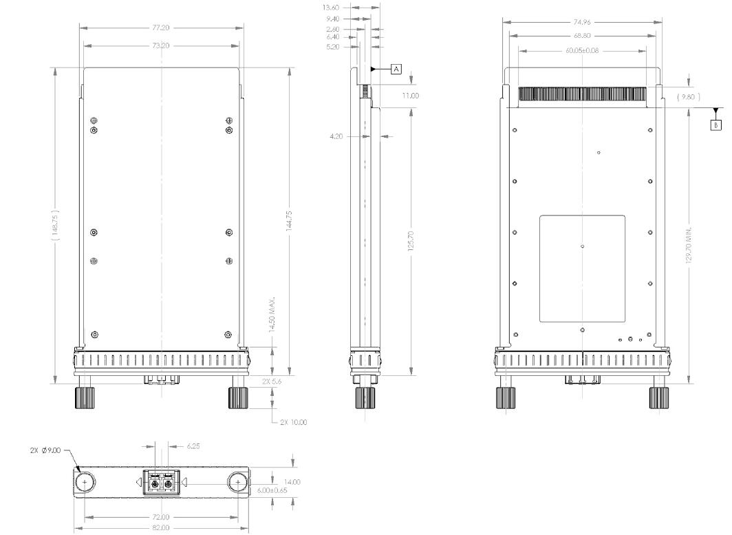
Package Dimensions
Applications
● OTN OTU4
● 100GBASE-ER4 100G Ethernet| Ordering Information |
|---|
| Date | Version | Description | Download |
|---|---|---|---|
| 2024-04-30 | V1.0 | Datasheet_100G CFP ER4 OTU4 40km_LA-CFP-ER4_OTU4.pdf | |
| Photo | Model | Description |
|---|
follow us