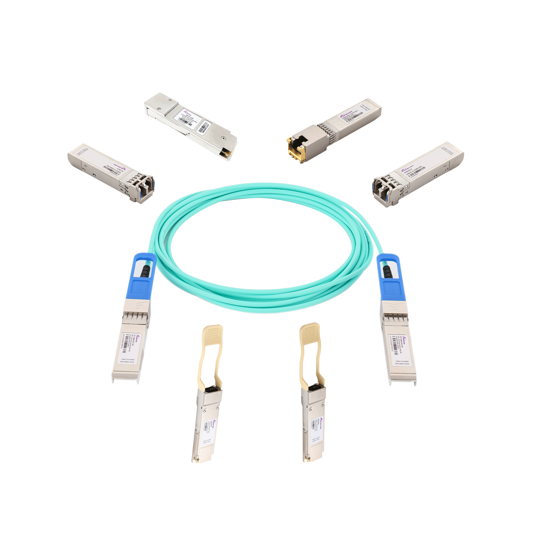
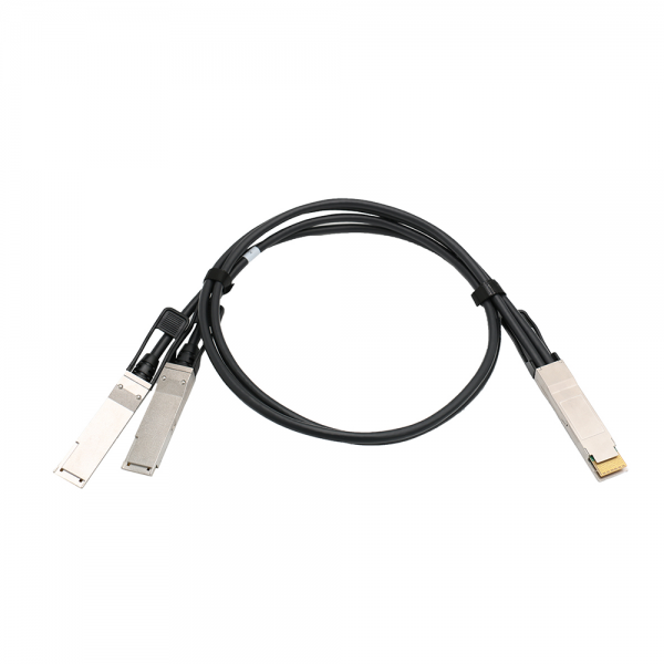

QSFP-DD (Double Density) Interconnect System and Cable Assemblies feature an eight-lane electrical interface that transmits up to 25G NRZ up to 200G aggregate.
QSFP-DD (Double Density) Interconnect System and Cable Assemblies feature an eight-lane electrical interface that transmits up to 25G NRZ up to 200G aggregate.
QSFP-DD (Double Density) Interconnect System and Cable Assemblies feature an eight-lane electrical interface that transmits up to 25G NRZ up to 200G aggregate.
QSFP-DD offers the same footprint as QSFP interconnects, making them backward compatible. The double density feature is an extended paddle card with two rows of high-speed context. QSFP-DD meets IEEE 802.3bj, InfiniBand EDR, and SAS 3.0 specifications, allowing these connectors and cable assemblies to function across a variety of next-generation technologies and applications.
100G QSFP28 passive cable assembly products, based on 4X25G structure, this product can well meet the next generation of 100G switches, servers, routers and other products application needs. The QSFP28 cable assembly is optimized to reduce crosstalk and ion loss and has excellent signal integrity, fully compliant with the next generation 100G Ethernet and InfiniBand EDR standards.
Wiring Diagram

Electrical Performance/Signal Integrity
|
Item |
Requirement |
Test Condition |
|||||||
|
Differential Impedance |
Cable Impedance |
105+5/-10Ω |
Rise time of 25ps (20 % - 80 %). |
||||||
|
Paddle Card Impedance |
100±10Ω |
||||||||
|
Cable Termination Impedance |
100±15Ω |
||||||||
|
Differential (Input/Output)
Return Loss SDD11/SDD22 |
{16.5-2√f 0.05≤f<4.1}
Return_loss(f)≥
{10.66-14log10(f/5.5) 4.1≤f≤19}
Where f is the frequency in GHz
Return loss(f) is the return loss at frequency f |
10MHz≤f≤19GHz |
|||||||
|
Differential to common-mode (Input/Output)
Return Loss SCD11/SCD22 |
{22-(20/25.78) f 0.01≤f<12.89}
Return_loss(f)≥
{15-(6/25.78) f 12.89≤f≤19}
Where f is the frequency in GHz
Return_loss(f) is the Differential to common-mode return loss at frequency f |
10MHz≤f≤19GHz |
|||||||
|
Common-mode to Common-mode (Input/Output)
Return Loss SCC11/SCC22 |
Return_loss(f)≥ 2dB 0.2≤f≤19
Where f is the frequency in GHz
Return_loss(f) is the common-mode to common-mode return loss at frequency f |
10MHz≤f≤19GHz |
|||||||
|
Differential Insertion Loss
(SDD21 Max.) |
Differential Insertion Loss Max. For TPa to TPb Excluding
Test fixture |
10MHz≤f≤19GHz |
|||||||
|
F
AWG |
1.25GHz |
2.5GHz |
5.0GHz |
7.0GHz |
10Ghz |
12.89Ghz |
|||
|
30(1m) Max. |
4.5dB |
5.4dB |
6.3dB |
7.5dB |
8.5dB |
10.5dB |
|||
|
30/28(3m) Max. |
7.5dB |
9.5dB |
12.2dB |
14.8dB |
18.0dB |
21.5dB |
|||
|
26(3m) Max. |
5.7dB |
7.2dB |
9.9 dB |
11.9dB |
14.1dB |
16.5dB |
|||
|
26/25(5m) Max. |
7.8dB |
10.0dB |
13.5dB |
16.0dB |
19.0dB |
22.0dB |
|||
|
Differential to common-mode Conversion Loss-Differential Insertion
Loss (SCD21-SDD21) |
{10 0.01≤f<12.89}
Conversion_loss(f) – IL(f)≥
{27-(29/22) f 12.89≤f﹤15.7}
Where f is the frequency in GHz
Conversion loss (f) is the cable assembly differential to common-mode conversion loss
IL(f) is the cable assembly ion loss |
10MHz≤f ≤19GHz |
|||||||
|
MDNEXT (multiple disturbers near-end crosstalk) |
≥26dB @12.89GHz |
10MHz≤f ≤19GHz |
|||||||
Other Electrical Performance
|
Item |
Requirement |
Test Condition |
|
Low Level Contact Resistance |
70milliohms Max. From initial. |
EIA-364-23: Apply a maximum voltage of 20mV
And a current of 100 mA. |
|
Insulation Resistance |
10Mohm (Min.) |
EIA364-21: AC300V 1minute |
|
Dielectric Withstanding Voltage |
NO disruptive disge. |
EIA-364-20: Apply a voltage of 300VDC for 1minute between adjacent terminals
And between adjacent terminals and ground. |
Environmental Performance
|
Item |
Requirement |
Test Condition |
|
Operating Temp. Range |
-20°C to +75°C |
Cable operating temperature range. |
|
Storage Temp. Range
(In packed condition) |
-40°C to +80°C |
Cable storage temperature range
in packed condition. |
|
Thermal Cycling Non-Powered |
No evidence of physical damage |
EIA-364-32D, Method A, -25 to 90C, 100 cycles, 15 min. dwells |
|
Salt Spraying |
48 hours salt spraying after shell
corrosive area less than 5%. |
EIA-364-26 |
|
Mixed Flowing Gas |
Pass electrical tests per 3.1 after
stressing. (For connector only) |
EIA-364-35 Class II, 14 days. |
|
Temp. Life |
No evidence of physical damage |
EIA-364-17C w/ RH, Damp heat 90℃ at 85% RH for 500hours then return to ambient |
|
Cable Cold Bend |
4H, No evidence of physical damage |
Condition: -20℃±2℃, mandrel diameter is 6 times the cable diameter. |
Mechanical and Physical Characteristics
|
Item |
Requirement |
Test Condition |
|
Vibration |
Pass electrical tests
per 3.1 after stressing. |
Clamp & vibrate per EIA-364-28E, TC-VII, test condition letter – D, 15 minutes in X, Y & Z axis. |
|
Cable Flex |
No evidence of physical damage |
Flex cable 180° for 20 cycles (±90° from nominal position) at 12 cycles per minute with a 1.0kg load applied to the cable jacket. Flex in the boot area 90º in each direction from vertical. Per EIA-364-41C |
|
Cable Plug Retention in Cage |
90N Min.
No evidence of physical damage |
Force to be applied axially with no damage to cage. Per SFF 8661 Rev 2.1
Pull on cable jacket approximately 1 ft behind cable plug. No functional damage to cable plug below 90N.
Per SFF-8432 Rev 5.0 |
|
Cable Retention in Plug |
90N Min.
No evidence of physical damage |
Cable plug is fixtured with the bulk cable hanging vertically. A 90N axial load is applied (gradually) to the cable jacket and held for 1 minute. Per EIA-364-38B |
|
Mechanical Shock |
Pass electrical tests
Per 3.1 after stressing. |
Clamp and shock per EIA-364-27B, TC-G, 3 times in 6 directions, 100g, 6ms. |
|
Cable Plug Insertion |
40N Max. (QSFP56) |
Per SFF8661 Rev 2.1 |
|
Cable plug Extraction |
30N Max. (QSFP56) |
Place axial load on de-latch to de-latch plug.
Per SFF8661 Rev 2.1 |
|
Durability |
50 cycles, No evidence of physical damage |
EIA-364-09, perform plug &unplug cycles: Plug and receptacle mate rate: 250times/hour. 50times for module (CONNECTOR TO PCB) |
Features
● MEET SFF-8636&QSFP-DD MSA
● MEET IEEE802.3bj&IEEE802.3 cd
● Support I2C two - line string interface, easy to control
● Support for hot plugging
● Low crosstalk
● Eight-lane electrical interface transmits up to 25Gbps NRZ
Applications
● Servers
● Routers
● Switches - Cellular infrastructure; Multi-platform service systems
Mechanical and Physical Characteristics
Both ends of the connector use protective sleeve protection, each into a separate anti-static bag.
<=2m: 200mm*300mm; >2m: 300mm*400mm

Outline Drawing

| Ordering Information |
|---|
| Date | Version | Description | Download |
|---|---|---|---|
| 2024-04-18 | V1.0 | Datasheet_Passive Direct Attach Copper Cable 200G QSFPDD to 2x100G QSFP28_V1.0 J | |
| Photo | Model | Description |
|---|
follow us