
200G QSFPDD To 2x100G QSFP28 breakout Active Optical Cable is designed for short-range multi-lane data communication and interconnect applications.
200G QSFPDD To 2x100G QSFP28 breakout Active Optical Cable is designed for short-range multi-lane data communication and interconnect applications.
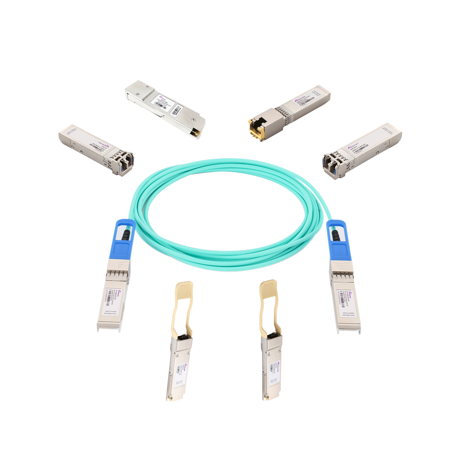
200G QSFPDD To 2x100G QSFP28 breakout Active Optical Cable is designed for short-range multi-lane data communication and interconnect applications. It integrates eight data lanes in each direction with 8x25.78125Gbps bandwidth. Each lane can operate at 25.78125Gbps up to 70 m using OM3 fiber or 100 m using OM4 fiber. These modules are designed to operate over multimode fiber systems using a nominal wavelength of 850nm. The electrical interface uses a 76 contact edge type connector. The optical interface uses a 24 fiber MTP (MPO) connector. This module incorporates technologies proven circuit and VCSEL technology to provide reliable long life, high performance, and consistent service.
Absolute Maximum Ratings
|
Parameter |
Symbol |
Min |
Max |
Unit |
|
Supply Voltage |
Vcc |
-0.3 |
3.6 |
V |
|
Input Voltage |
Vin |
-0.3 |
Vcc+0.3 |
V |
|
Storage Temperature |
Tst |
-20 |
85 |
ºC |
|
Case Operating Temperature |
Top |
0 |
70 |
ºC |
|
Humidity(non-condensing) |
Rh |
5 |
95 |
% |
Recommended Operating Conditions
|
Parameter |
Symbol |
Min |
Typical |
Max |
Unit |
|
Supply Voltage |
Vcc |
3.13 |
3.3 |
3.47 |
V |
|
Operating Case temperature |
Tca |
0 |
|
70 |
ºC |
|
Data Rate Per Lane |
fd |
|
25.78125 |
|
Gbps |
|
Humidity |
Rh |
5 |
|
85 |
% |
|
Power Dissipation |
Pm |
|
2 |
2.5 |
W |
|
Fiber Bend Radius |
Rb |
3 |
|
|
cm |
Electrical Specifications
|
Parameter |
Symbol |
Min |
Typical |
Max |
Unit |
|
Differential input impedance |
Zin |
90 |
100 |
110 |
ohm |
|
Differential Output impedance |
Zout |
90 |
100 |
110 |
ohm |
|
Differential input voltage amplitude aAmplitude |
ΔVin |
300 |
|
1100 |
mVp-p |
|
Differential output voltage amplitude |
ΔVout |
500 |
|
800 |
mVp-p |
|
Skew |
Sw |
|
|
300 |
ps |
|
Bit Error Rate1 |
BER |
|
|
E-12 |
|
|
Input Logic Level High2 |
VIH |
2.0 |
|
VCC |
V |
|
Input Logic Level Low2 |
VIL |
0 |
|
0.8 |
V |
|
Output Logic Level High3 |
VOH |
VCC-0.5 |
|
VCC |
V |
|
Output Logic Level Low3 |
VOL |
0 |
|
0.4 |
V |
Note:
1. BER=10^-12; PRBS 2^31-1@25.78125Gbps .
2. Differential input voltage amplitude is measured between TxnP and TxnN.
3. Differential output voltage amplitude is measured between RxnP and RxnN.
Optical Characteristics
|
Parameter |
Symbol |
Min |
Typical |
Max |
Unit |
Notes |
|
Transmitter |
||||||
|
Centre Wavelength |
λc |
840 |
850 |
860 |
nm |
- |
|
RMS spectral width |
∆λ |
- |
- |
0.6 |
nm |
- |
|
Average launch power, each lane |
Pout |
-8.4 |
- |
2.4 |
dBm |
- |
|
Optical Modulation Amplitude
(OMA),each lane |
OMA |
-6.4 |
|
3 |
dBm |
- |
|
Transmitter and dispersion eye closure(TDEC),each lane |
TDEC |
|
|
4.3 |
dB |
|
|
Extinction Ratio |
ER |
3 |
- |
- |
dB |
- |
|
Average launch power of OFF
transmitter, each lane |
|
|
|
-30 |
dB |
- |
|
Eye Mask coordinates:
X1, X2, X3, Y1, Y2, Y3 |
SPECIFICATION VALUES
{0.3,0.38,0.45,0.35,0.41.0.5} |
Hit Ratio = 5x10⁻⁵
|
||||
|
Receiver |
||||||
|
Centre Wavelength |
λc |
840 |
850 |
860 |
nm |
- |
|
Stressed receiver sensitivity in OMA |
|
|
|
-5.2 |
dBm |
1 |
|
Maximum Average power at receiver , each lane
input, each lane |
|
|
|
2.4 |
dBm |
- |
|
Minimum Average power at receiver , each lane |
|
|
|
-10.3 |
dBm |
|
|
Receiver Reflectance |
|
|
|
-12 |
dB |
- |
|
LOS Assert |
|
-30 |
|
|
dBm |
- |
|
LOS De-Assert – OMA |
|
|
|
-7.5 |
dBm |
- |
|
LOS Hysteresis |
|
0.5 |
|
|
dB |
- |
Pin Deions (100G QSFP28 SR4)
|
Pin |
Logic |
Symbol |
Name/Deion |
Ref. |
|
1 |
|
GND |
Module Ground |
1 |
|
2 |
CML-I |
Tx2- |
Transmitter inverted data input |
|
|
3 |
CML-I |
Tx2+ |
Transmitter non-inverted data input |
|
|
4 |
|
GND |
Module Ground |
1 |
|
5 |
CML-I |
Tx4- |
Transmitter inverted data input |
|
|
6 |
CML-I |
Tx4+ |
Transmitter non-inverted data input |
|
|
7 |
|
GND |
Module Ground |
1 |
|
8 |
LVTTL-I |
MODSEIL |
Module Select |
2 |
|
9 |
LVTTL-I |
ResetL |
Module Reset |
2 |
|
10 |
|
VCCRx |
+3.3v Receiver Power Supply |
|
|
11 |
LVCMOS-I |
SCL |
2-wire Serial interface clock |
2 |
|
12 |
LVCMOS-I/O |
SDA |
2-wire Serial interface data |
2 |
|
13 |
|
GND |
Module Ground |
1 |
|
14 |
CML-O |
RX3+ |
Receiver non-inverted data output |
|
|
15 |
CML-O |
RX3- |
Receiver inverted data output |
|
|
16 |
|
GND |
Module Ground |
1 |
|
17 |
CML-O |
RX1+ |
Receiver non-inverted data output |
|
|
18 |
CML-O |
RX1- |
Receiver inverted data output |
|
|
19 |
|
GND |
Module Ground |
1 |
|
20 |
|
GND |
Module Ground |
1 |
|
21 |
CML-O |
RX2- |
Receiver inverted data output |
|
|
22 |
CML-O |
RX2+ |
Receiver non-inverted data output |
|
|
23 |
|
GND |
Module Ground |
1 |
|
24 |
CML-O |
RX4- |
Receiver inverted data output |
|
|
25 |
CML-O |
RX4+ |
Receiver non-inverted data output |
|
|
26 |
|
GND |
Module Ground |
1 |
|
27 |
LVTTL-O |
ModPrsL |
Module Present, internal pulled down to GND |
|
|
28 |
LVTTL-O |
IntL |
Interrupt output, should be pulled up on host board |
2 |
|
29 |
|
VCCTx |
+3.3v Transmitter Power Supply |
|
|
30 |
|
VCC1 |
+3.3v Power Supply |
|
|
31 |
LVTTL-I |
LPMode |
Low Power Mode |
2 |
|
32 |
|
GND |
Module Ground |
1 |
|
33 |
CML-I |
Tx3+ |
Transmitter non-inverted data input |
|
|
34 |
CML-I |
Tx3- |
Transmitter inverted data input |
|
|
35 |
|
GND |
Module Ground |
1 |
|
36 |
CML-I |
Tx1+ |
Transmitter non-inverted data input |
|
|
37 |
CML-I |
Tx1- |
Transmitter inverted data input |
|
|
38 |
|
GND |
Module Ground |
1 |
Notes:
1. Module circuit ground is isolated from module chassis ground within the module.
2. Open collector; should be pulled up with 4.7k – 10k ohms on host board to a voltage between 3.15Vand 3.6V.
Pin Deion (200G QSFP DD SR8)
|
Pin |
Logic |
Symbol |
Name/Deion |
|
1 |
|
GND |
Module Ground 1 |
|
2 |
CML-I |
Tx2- |
Transmitter inverted data input |
|
3 |
CML-I |
Tx2+ |
Transmitter non-inverted data input |
|
4 |
|
GND |
Module Ground 1 |
|
5 |
CML-I |
Tx4- |
Transmitter inverted data input |
|
6 |
CML-I |
Tx4+ |
Transmitter non-inverted data input |
|
7 |
|
GND |
Module Ground 1 |
|
8 |
LVTTL-I |
MODSEIL |
Module Select 2 |
|
9 |
LVTTL-I |
ResetL |
Module Reset 2 |
|
10 |
|
VCCRx |
+3.3V Receiver Power Supply |
|
11 |
LVCMOS-I/O |
SCL |
2-wire Serial interface clock 2 |
|
12 |
LVCMOS-I/O |
SDA |
2-wire Serial interface data 2 |
|
13 |
|
GND |
Module Ground 1 |
|
14 |
CML-O |
RX3+ |
Receiver non-inverted data output |
|
15 |
CML-O |
RX3- |
Receiver inverted data output |
|
16 |
|
GND |
Module Ground 1 |
|
17 |
CML-O |
RX1+ |
Receiver non-inverted data output |
|
18 |
CML-O |
RX1- |
Receiver inverted data output |
|
19 |
|
GND |
Module Ground 1 |
|
20 |
|
GND |
Module Ground 1 |
|
21 |
CML-O |
RX2- |
Receiver inverted data output |
|
22 |
CML-O |
RX2+ |
Receiver non-inverted data output |
|
23 |
|
GND |
Module Ground 1 |
|
24 |
CML-O |
RX4- |
Receiver inverted data output |
|
25 |
CML-O |
RX4+ |
Receiver non-inverted data output |
|
26 |
|
GND |
Module Ground 1 |
|
27 |
LVTTL-O |
ModPrsL |
Module Present, internal pulled down to GND 2 |
|
28 |
LVTTL-O |
IntL |
Interrupt output, should be pulled up on host board 2 |
|
29 |
|
VCCTx |
+3.3V Transmitter Power Supply |
|
30 |
|
VCC1 |
+3.3V Power Supply |
|
31 |
LVTTL-I |
InitMode |
Initialization mode; In legacy QSFP applications, the InitMode pad is called LPMODE 2 |
|
32 |
|
GND |
Module Ground 1 |
|
33 |
CML-I |
Tx3+ |
Transmitter non-inverted data input |
|
34 |
CML-I |
Tx3- |
Transmitter inverted data input |
|
35 |
|
GND |
Module Ground 1 |
|
36 |
CML-I |
Tx1+ |
Transmitter non-inverted data input |
|
37 |
CML-I |
Tx1- |
Transmitter inverted data input |
|
38 |
|
GND |
Module Ground 1 |
|
39
|
|
GND |
Module Ground 1 |
|
40
|
CML-I |
Tx6- |
Transmitter inverted data input |
|
41 |
CML-I |
Tx6+ |
Transmitter non-inverted data input |
|
42 |
|
GND |
Module Ground 1 |
|
43 |
CML-I |
Tx8- |
Transmitter inverted data input |
|
44 |
CML-I |
Tx8+ |
Transmitter non-inverted data input |
|
45 |
|
GND |
Module Ground 1 |
|
46 |
|
Reserved |
For future use |
|
47 |
|
VS1 |
Module Vender Specific 1 |
|
48 |
|
VCCRx1 |
+3.3V Power Supply |
|
49 |
|
VS2 |
Module Vender Specific 2 |
|
50 |
|
VS3 |
Module Vender Specific 3 |
|
51 |
|
GND |
Module Ground 1 |
|
52 |
CML-O |
RX7+ |
Receiver non-inverted data output |
|
53 |
CML-O |
RX7- |
Receiver inverted data output |
|
54 |
|
GND |
Module Ground 1 |
|
55 |
CML-O |
RX5+ |
Receiver non-inverted data output |
|
56 |
CML-O |
RX5- |
Receiver inverted data output |
|
57 |
|
GND |
Module Ground 1 |
|
58 |
|
GND |
Module Ground 1 |
|
59 |
CML-O |
RX6- |
Receiver inverted data output |
|
60 |
CML-O |
RX6+ |
Receiver non-inverted data output |
|
61 |
|
GND |
Module Ground 1 |
|
62 |
CML-O |
RX8- |
Receiver inverted data output |
|
63 |
CML-O |
RX8+ |
Receiver non-inverted data output |
|
64 |
|
GND |
Module Ground 1 |
|
65 |
|
NC |
N0 Connect |
|
66 |
|
Reserved |
For future use |
|
67 |
|
VCCTx1 |
+3.3V Power Supply |
|
68 |
|
VCC2 |
+3.3V Power Supply |
|
69 |
|
Reserved |
For future use |
|
70 |
|
GND |
Module Ground 1 |
|
71 |
CML-I |
Tx7+ |
Transmitter non-inverted data input |
|
72 |
CML-I |
Tx7- |
Transmitter inverted data input |
|
73 |
|
GND |
Module Ground 1 |
|
74 |
CML-I |
Tx5+ |
Transmitter non-inverted data input |
|
75 |
CML-I |
Tx5- |
Transmitter inverted data input |
|
76 |
|
GND |
Module Ground 1 |
Note:
1. Module circuit ground is isolated from module chassis ground within the module.
2. Open collector should be pulled up with 4.7K to 10K ohms on host board to a voltage between 3.15V and 3.6V.
Features
● Hot-pluggable QSFP DD/QSFP28 form factor
● 8 channels full-duplex transceiver module
● Supports data rate up to 26Gbps per channel
● 8 channels 850nm VCSEL array and PIN photo-detector array
● Internal CDR circuits within receiver and transmitter data paths
● Supports CDR bypass via I2C controlled
● Low power consumption: 200GBASE-SR8 QSFP DD<4w and 100GBASE-SR4 QSFP28<2.5w
● Maximum link length of 70m on OM3 MMF and 100m on OM4 MMF
● Single MTP/MPO receptacle
● Built-in digital diagnostic monitoring functionality
● I2C management interface
● Commercial case temperature of 0 to 70°C
● Single 3.3V power supply
● RoHS 2.0 compliant (lead free)
Applications
● IEEE 802.3cd 200GBASE SR8
● IEEE 802.3bm 100GBASE SR4
Module Block Diagram

Figure 1. 100G QSFP28 SR4 Module Block Diagram

Figure 2. 200G QSFP DD Module Block Diagram

Figure 3. AOC Block Diagram

Figure 4. Electrical Pin-out Details
ModSelL Pin
The ModSelL is an input pin. When held low by the host, the module responds to 2-wire serial communication
commands. The ModSelL allows the use of multiple QSFP modules on a single 2-wire interface bus. When
the ModSelL is “High”, the module will not respond to any 2-wire interface communication from the host.
ModSelL has an internal pull-up in the module.
ResetL Pin
Reset. LPMode_Reset has an internal pull-up in the module. A low level on the ResetL pin for longer than the
minimum pulse length (t_Reset_init) initiates a complete module reset, returning all user module settings to
their default state. Module Reset Assert Time (t_init) starts on the rising edge after the low level on the
ResetL pin is released. During the execution of a reset (t_init) the host shall disregard all status bits until the
module indicates a completion of the reset interrupt. The module indicates this by posting an IntL signal with
the Data_Not_Ready bit negated. Note that on power up (including hot ion) the module will post this
completion of reset interrupt without requiring a reset.
LPMode Pin
QSFP28 SR4 operate in the low power mode (less than 1.5 W power consumption)
This pin active high will decrease power consumption to less than 1W.
ModPrsL Pin
ModPrsL is pulled up to Vcc on the host board and grounded in the module. The ModPrsL is asserted “Low”
when the module is ed and deasserted “High” when the module is physically absent from the host connector.
IntL Pin
IntL is an output pin. When “Low”, it indicates a possible module operational fault or a status critical to the
host system. The host identifies the source of the interrupt by using the 2-wire serial interface. The IntL pin is
an open collector output and must be pulled up to Vcc on the host board.
Power Supply Filtering (100G QSFP28 SR4)
The host board should use the power supply filtering shown in Figure5.

Figure 5. Host Board Power Supply Filtering
Memory Map (100G QSFP28 SR4)

Figure 5. Host Board Power Supply Filtering

Figure 6. Low Memory Map

Figure 7. Page 03 Memory Map

Figure 8. Page 00 Memory Map
Page02 is User EEPROM and its format decided by user.
The detail deion of low memory and page00.page03 upper memory please see SFF-8436 document.

Figure 9. Electrical Pin-out Details
ModSelL Pin
The ModSelL is an input signal that must be pulled to Vcc in the QSFP-DD module. When held low by the host, the module responds to 2-wire serial communication commands. The ModSelL allows the use of multiple QSFP-DD modules on a single 2-wire interface bus. When ModSelL is “High”, the module shall not respond to or acknowledge any 2-wire interface communication from the host.
ResetL Pin
The ResetL signal shall be pulled to Vcc in the module. A low level on the ResetL signal for longer than the minimum pulse length (t_Reset_init) initiates a complete module reset, returning all user module settings to their default state.
InitMode Pin
InitMode is an input signal. The InitMode signal must be pulled up to Vcc in the QSFP-DD module (see Table 2). The InitMode signal allows the host to define whether the QSFP-DD module will initialize under host software control (InitMode asserted High) or module hardware control (InitMode deasserted Low). Under host software control, the module shall remain in Low Power Mode until software enables the transition to High Power Mode, as defined in the QSFP-DD Management Interface Specification. Under hardware control (InitMode de-asserted Low), the module may immediately transition to High Power Mode after the management interface is initialized. The host shall not change the state of this signal while the module is present. In legacy QSFP applications, this signal is named LPMode. See SFF-8679 for LPMode signal deion.
ModPrsL Pin
ModPrsL must be pulled up to Vcc Host on the host board and pulled low in the module. The ModPrsL is asserted “Low” when the module is ed. The ModPrsL is deasserted “High” when the module is physically absent from the host connector due to the pull up resistor on the host board.
IntL Pin
IntL is an output signal. The IntL signal is an open collector output and must be pulled to Vcc Host on the host board (see Table 2). When the IntL signal is asserted Low it indicates a change in module state, a possible module operational fault or a status critical to the host system. The host identifies the source of the interrupt using the 2-wire serial interface. The IntL signal is deasserted “High” after all set interrupt flags are read..
Power Supply Filtering (200G QSFP DD SR8)
The host board should use the power supply filtering shown in Figure 10.

Figure 10. Host Board Power Supply Filtering
Memory Map (200G QSFP DD SR8)

Figure 11. QSFP DD Memory Map

Figure 12. Low Memory Map

Figure 13. Page 03 Memory Map


Figure 14. Page 00 Memory Map
Page02 is User EEPROM and its format decided by user.
The detail deion of low memory and Page 00.Page 03 upper memory please see SFF-8436 document.
Outline Drawing

| Ordering Information |
|---|
| Date | Version | Description | Download |
|---|---|---|---|
| 2024-04-18 | V2.0 | Datasheet_Active Optical Cable 200G QSFP-DD SR8 to 2x100GBASE QSFP28 SR4_V2.0 YF | |
| Photo | Model | Description |
|---|
follow us