2x100GBASE-SR4 QSFPDD transceiver is one kind of parallel transceiver, VCSEL and PIN array package is the key technique, through I2C system can contact with module. It is a Eight-Channel, Pluggable, Parallel, Fiber-Optic QSFP Double Density for 2x100 Gigabit Ethernet applications, high performance module for short-range multi-lane data communication and interconnect applications. It integrates eight data lanes in each direction with 8x25.78125Gbps bandwidth. Each lane can operate at 25.78125Gbps up to 70 m using OM3 fiber or 100 m using OM4 fiber. These modules are designed to operate over multimode fiber systems using a nominal wavelength of 850nm. The electrical interface uses a 76 contact edge type connector. The optical interface uses an 24 fiber MTP (MPO) connector. This module incorporates proven circuit and VCSEL technology to provide reliable long life, high performance, and consistent service.
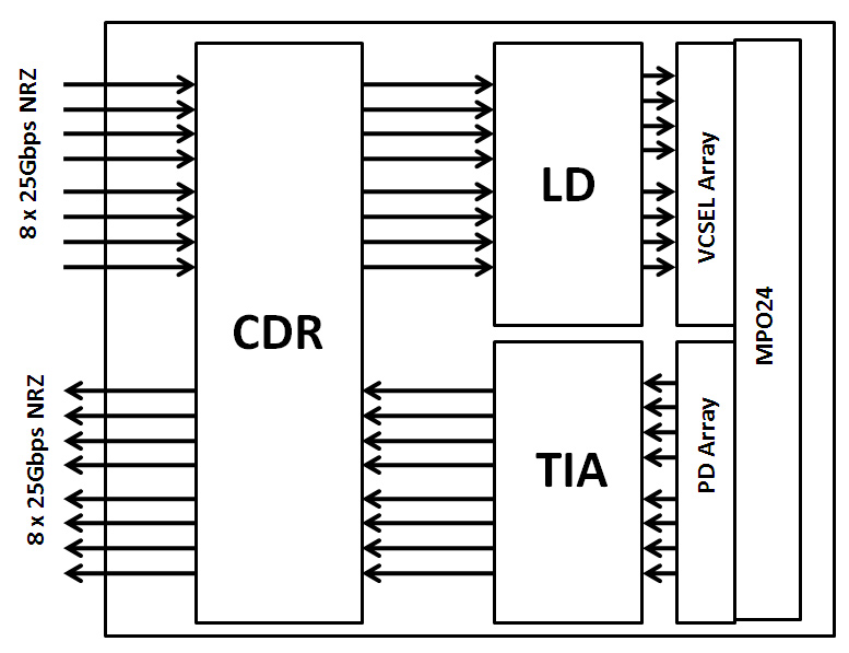
Figure 1. Module Block Diagram
Features
● 8 channels full-duplex transceiver modules
● Transmission data rate up to 26Gbps per channel
● 8 channels 850nm VCSEL array
● 8 channels PIN photo detector array
● Internal CDR circuits on both receiver and transmitter channels
● Support CDR bypass
● Low power consumption <4W
● Hot Pluggable QSFP DD form factor
● Maximum link length of 70m on OM3 Multimode Fiber (MMF)and 100m on OM4 MMF
● MPO24 connector receptacle
● Operating case temperature 0°C to +70°C
● 3.3V power supply voltage
Pin Deion
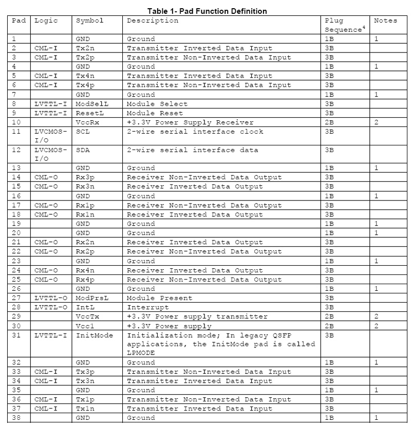
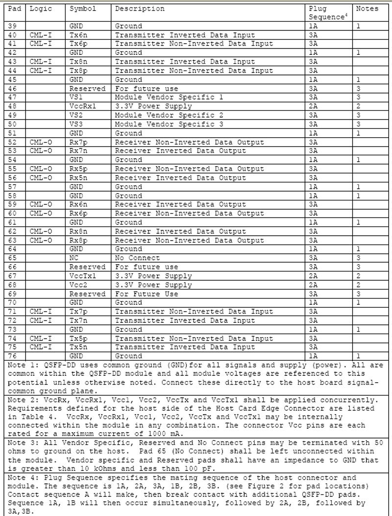
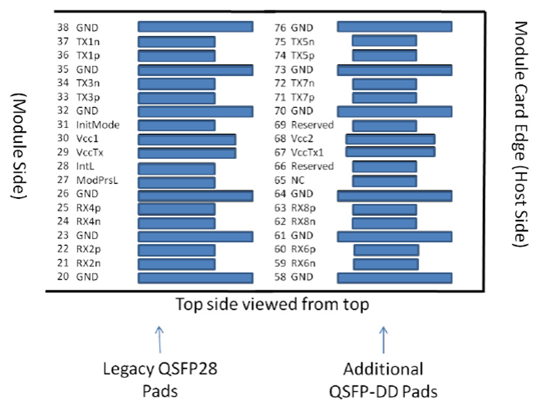
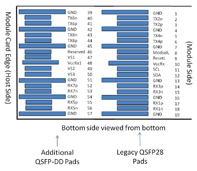
Figure 2. Electrical Pin-out Details
ModSelL Pin
The ModSelL is an input signal that must be pulled to Vcc in the QSFP-DD module. When held low by the host, the module responds to 2-wire serial communication commands. The ModSelL allows the use of multiple QSFP-DD modules on a single 2-wire interface bus. When ModSelL is “High”, the module shall not respond to or acknowledge any 2-wire interface communication from the host.
In order to avoid conflicts, the host system shall not attempt 2-wire interface communications within the ModSelL de-assert time after any QSFP-DD modules are deed. Similarly, the host must wait at least for the period of the ModSelL assert time before communicating with the newly ed module. The assertion and de-asserting periods of different modules may overlap as long as the above timing requirements are met.
ResetL Pin
The ResetL signal shall be pulled to Vcc in the module. A low level on the ResetL signal for longer than the minimum pulse length (t_Reset_init) (See Table 13 ) initiates a complete module reset, returning all user module settings to their default state.
InitMode Pin
InitMode is an input signal. The InitMode signal must be pulled up to Vcc in the QSFP-DD module. The InitMode signal allows the host to define whether the QSFP-DD module will initialize under host software control (InitMode asserted High) or module hardware control (InitMode deasserted Low). Under host software control, the module shall remain in Low Power Mode until software enables the transition to High Power Mode, as defined in Section 7.5. Under hardware control (InitMode de-asserted Low), the module may immediately transition to High Power Mode after the management interface is initialized. The host shall not change the state of this signal while the module is present. In legacy QSFP applications, this signal is named LPMode. See SFF-8679 for signal deion.
ModPrsL Pin
ModPrsL must be pulled up to Vcc Host on the host board and grounded in module. The ModPrsL is asserted “Low” when module is ed and deasserted “High” when module is physically absent from host connector.
IntL Pin
IntL is an output signal. The IntL signal is an open collector output and must be pulled to Vcc Host on the host board. When the IntL signal is asserted Low it indicates a change in module state, a possible module operational fault or a status critical to the host system. The host identifies the source of the interrupt using the 2-wire serial interface. The IntL signal is deasserted “High” after all set interrupt flags are read.
Power Supply Filtering
The host board should use the power supply filtering shown in Figure3.
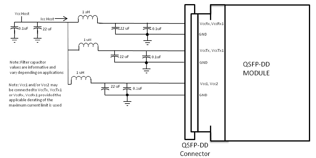
Figure 3. Host Board Power Supply Filtering
Optical Interface Lanes and Assignment
The optical interface port is a male MPO24 connector .

Figure 4. Optical Receptacle and Channel Orientation
DIAGNOSTIC MONITORING INTERFACE (OPTIONAL)
Digital diagnostics monitoring function is available on all QSFP DD products. A 2-wire serial interfaceprovides user to contact with module. The structure of the memory is shown in Figure 5. The memory space is arranged into a lower, single page, address space of 128 bytes and multiple upper address space pages. This structure permits timely access to addresses in the lower page, e.g. Interrupt Flags and Monitors. Less time critical entries, e.g. serial ID information and threshold settings, are available with the Page Select function. The structure also provides address expansion by adding additional upper pages as needed. The interface address used is A0xh and is mainly used for time critical data like interrupt handling in order to enable a one-time-read for all data related to an interrupt situation. After an interrupt, IntL, has been asserted, the host can read out the flag field to determine affected channel and type of flag.
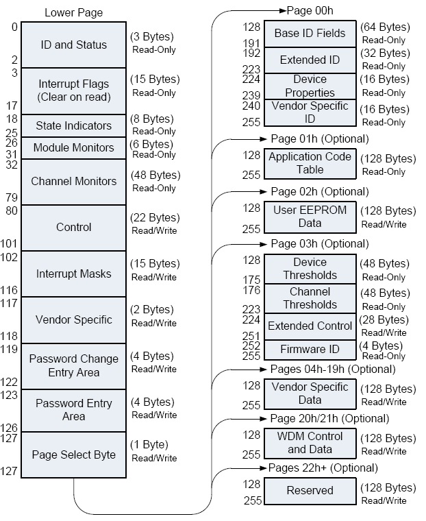
Figure 5. QSFP DD Memory Map

Figure 6. Low Memory Map

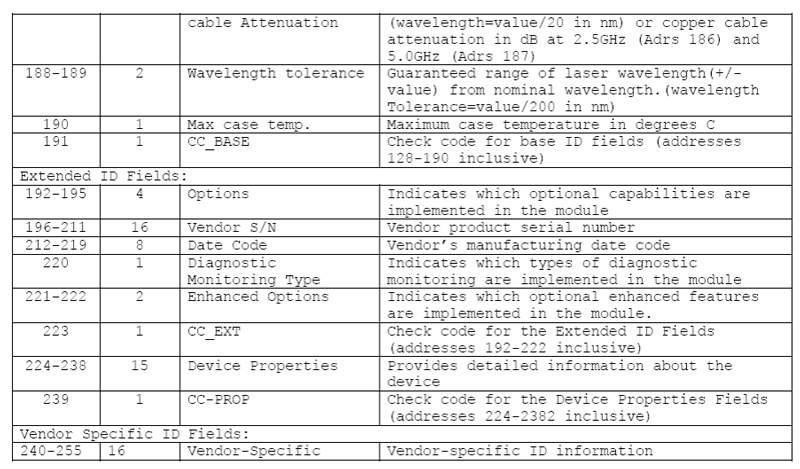
Figure7. Page 00 Memory Map
Timing for Soft Control and Status Functions
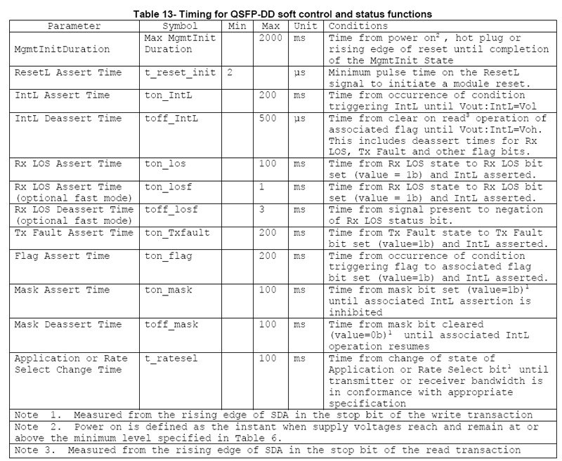
Figure 9. Timing Specifications
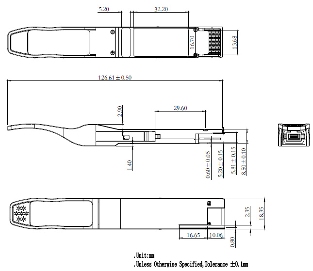
Outline Drawing (mm)
Absolute Maximum Ratings
Parameter | Symbol | Min | Max | Unit |
Supply Voltage | Vcc | -0.3 | 3.6 | V |
Input Voltage | Vin | -0.3 | Vcc+0.3 | V |
Storage Temperature | Tst | -20 | 85 | ºC |
Case Operating Temperature | Top | 0 | 70 | ºC |
Humidity(non-condensing) | Rh | 5 | 95 | % |
Recommended Operating Conditions
Parameter | Symbol | Min | Typical | Max | Unit |
Supply Voltage | Vcc | 3.13 | 3.3 | 3.47 | V |
Operating Case temperature | Tca | 0 |
| 70 | ºC |
Data Rate Per Lane | fd |
| 25.78125 |
| Gbps |
Humidity | Rh | 5 |
| 85 | % |
Power Dissipation | Pm |
|
| 4 | W |
Electrical Specifications
Parameter | Symbol | Min | Typical | Max | Unit |
Differential input impedance | Zin | 90 | 100 | 110 | ohm |
Differential Output impedance | Zout | 90 | 100 | 110 | ohm |
Differential input voltage amplitude aAmplitude | ΔVin | 300 |
| 1100 | mVp-p |
Differential output voltage amplitude | ΔVout | 500 |
| 800 | mVp-p |
Skew | Sw |
|
| 300 | ps |
Bit Error Rate | BER |
|
| 5E-5 |
|
Input Logic Level High | VIH | 2.0 |
| VCC | V |
Input Logic Level Low | VIL | 0 |
| 0.8 | V |
Output Logic Level High | VOH | VCC-0.5 |
| VCC | V |
Output Logic Level Low | VOL | 0 |
| 0.4 | V |
Note:
1. BER=5E-5; PRBS 2^31-1@25.78125Gbps. Pre-FEC
2. Differential input voltage amplitude is measured between TxnP and TxnN.
3. Differential output voltage amplitude is measured between RxnP and RxnN.
Optical Characteristics
Table 3 - Optical Characteristics
Parameter | Symbol | Min | Typical | Max | Unit | Notes |
Transmitter |
Centre Wavelength | λc | 840 | 850 | 860 | nm | - |
RMS spectral width | ∆λ | - | - | 0.6 | nm | - |
Average launch power, each lane | Pout | -8.4 | - | 2.4 | dBm | - |
Optical Modulation Amplitude (OMA),each lane | OMA | -6.4 |
| 3 | dBm | - |
Transmitter and dispersion eye closure(TDEC),each lane | TDEC |
|
| 4.3 | dB |
|
Extinction Ratio | ER | 3 | - | - | dB | - |
Average launch power of OFF transmitter, each lane |
|
|
| -30 | dB | - |
Eye Mask coordinates: X1, X2, X3, Y1, Y2, Y3 | SPECIFICATION VALUES {0.3,0.38,0.45,0.35,0.41.0.5} | Hit Ratio = 5x10⁻⁵
|
Receiver |
Centre Wavelength | λc | 840 | 850 | 860 | nm | - |
Stressed receiver sensitivity in OMA |
|
|
| -5.2 | dBm | 1 |
Maximum Average power at receiver, each lane input, each lane |
|
|
| 2.4 | dBm | - |
Minimum Average power at receiver, each lane
|
|
|
| -10.3 | dBm |
|
Receiver Reflectance |
|
|
| -12 | dB | - |
LOS Assert |
| -30 |
|
| dBm | - |
LOS De-Assert – OMA |
|
|
| -7.5 | dBm | - |
LOS Hysteresis |
| 0.5 |
|
| dB | - |
Note:
1.Measured with conformance test signal at TP3 for BER = 5E-5 Per-FEC
Applications
● IEEE 802.3bm 100GBASE SR4
 Internet Data Center
 FAQ
FAQ Company News
 About Us
 Data Center Switch
  Enterprise Switch
  Industrial Switch
  Access Switch
  Integrated Network
  Optical Module & Cable





 Call us on:
  Email Us:
  Room 2106, 3D Building, Tianan Yungu Industrial Park, Xuegang Road No.2018, Bantian, Longgang, Shenzhen, P.R.C.